


Le Tonkinois Varnish
B & D Murkin
UK main importers for
Le Tonkinois varnish
Flexidisc sander
Eberspacher Low voltage shut-off problems
How to identify and rectify
Low voltage is probably the most common Eberspacher fault but very little information is given elsewhere on solving the problem. The most obvious causes are due to low battery charge or a battery in poor condition, simple to cure, just recharge or replace. Leisure batteries often are not replaced as they age and can deteriorate without users realising. The internal charge condition indicator may still show as good especially if the battery is continuously float charged. If not 100% sure easiest way to eliminate is to temporarily replace the battery with a known good vehicle battery. If the battery is not the culprit the fault can be very inconsistent and perplexing. Simply turning on something like a light can be the difference between working and failing when the voltage is marginal. Typically an Eberspacher heater might fail to start; often on a cold dark evening; then starts ok next day. It always works perfectly when taken to a servicing agent. Understanding why will save hours of cursing and kicking the Eberspacher in the frustrated hope it will suddenly start working! This page is based on 12v Eberspacher D1LC compact, D2 and D4 heaters but the information is applicable to all Eberspacher air and water models with a low voltage cut off. Check the quoted cut-
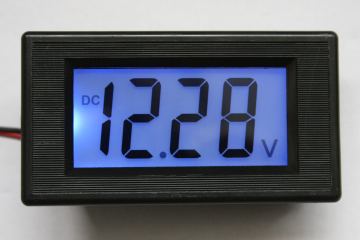
The blue back-
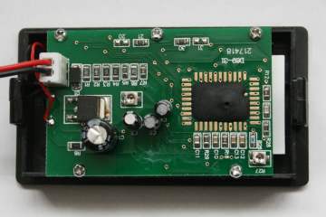
The rear of the voltmeter is not enclosed.
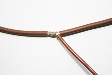
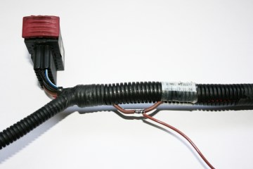
Joint with good sound mechanical contact before soldering.
Joint soldered, ready for insulating before placing inside the loom.
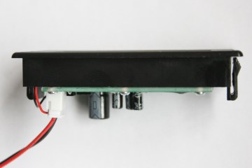
Side view showing one of the retaining clips.
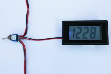
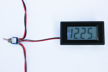
Measuring battery voltage.
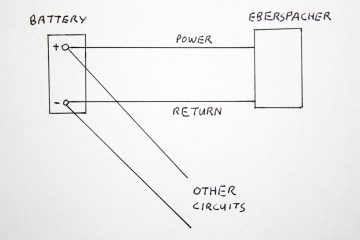
Typical power wiring to Eberspacher, fuses etc are not shown.
In a typical installation the battery powers various items; such as lighting, radio, tv, inverter as well as the heater. The battery is usually charged from the engine but may be from a separate battery charger.
Two wires from the battery go to the Eberspacher.
In some installations the chassis is used as the return wire (also referred to as negative, ground or 0v ).
To the majority of non-
The battery gives out a constant 12v supply which only changes when the battery runs flat.
The voltage at the far end of the wires must be the same as at the battery terminals.
If only this was true.
Firstly the battery
The output is anything but a constant 12v. The voltage changes depending upon how much charge remains in the battery. Typically after 6 hours rest with no current loading 100% charged 12.7v, 60% charged 12.2v, fully discharged 11.4v
The voltage changes with the total current drawn from it; more current drops the voltage.
One example no load 12.2v, 20 amps 11.4v
The voltage drops a small amount with low temperature, about 0.1v drop at 32 degrees F.
Charging the battery raises the voltage considerably; it also warms the battery. When the charging stops the voltage drops; it then drops more over a couple of hours or so.
Low temperature also reduces the capacity of the battery.
Add in the effects of aging and deterioration of the battery with use and you can see why low voltage causes intermittent and unpredictable problems.
Secondly the connecting cables -
Wire is not lossless; all cable heats up slightly as it passes current. Each electrical connection also has losses. The losses in the wire and connections reduce the voltage reaching the heater.
It is very easy to make a mistake and to fit a power supply cable that is too thin without realising that causes a problem. For example the Airtronic D2 takes about 8 amps maximum, wiring tables show 1 mm2 cable is rated up to about 14 amps. If you did use 1 mm2 cable it would carry the current but the voltage drop would easily become excessive. Heavier cables are normally required to reduce the total voltage drop.
For a D2 / D4 Eberspacher recommend 4 mm2 wires for up to 2.5m individual wire length; ie 2.5m positive wire and 2.5m return wire. Increase the cable size to 6 mm2 up to 4m, and 10 mm2 or more for longer runs. That should give a cable loss of 0.25v or less.
The length calculation should include cables from the battery terminal to the connection point.
Many other models take about 20 amps during starting so recommended cable sizes are doubled.
The problem
When the voltage at the Eberspacher drops to 10.5 volts lasting for 20 seconds it shuts down. (10.2 volts for some models) During starting the glow plug takes about 8 amps for a D2 or D4, the older models take about 20 amps. This is when the voltage drop will be worst and most low voltage problems occur. The usual symptom is the heater fan runs for about 20 to 45 seconds during starting, then the unit shuts down.
Note this voltage must be measured at the Eberspacher, the voltage at the battery end of the cables will be higher. The voltage can drop below 10.5 volts and not shut down the heater if it starts before 20 seconds.
As the battery discharges lower voltage can cut the heater off when running. In each case it will usually make another attempt to start. See Testing -
Eberspacher quote all electrical measurements can vary by 10%, however the voltage cutoffs are set quite accurately.
What to do if low voltage cut off is the problem
A short -
The permanent solutions are one or more of the following:
If the battery is in poor condition replace it. When engine batteries deteriorate the engine fails to start so they quickly get replaced. Leisure batteries do not supply such high currents so can deteriorate very badly without being noticed. Marina based boats may have a float charger connected permanently which can hide serious degradation. One user only found his leisure battery was bad when his Airtronic D2 failed with a blown ECU. The dealer tested it (fault code 99) and asked the user if he had battery problems. With the charger switched off the voltage at the Airtronic D2 dropped to 9.5 volts during starting. With a good battery it was 12v. The Eberspacher had been drawing power from the CTEK charger and the faulty leisure battery was unable to smooth out the battery charger ripple causing an expensive ECU failure. I also tested three old 110 Ah leisure batteries that I used on shows, they were going flat far earlier than when new. The ampere hour capacity of the best one had dropped to below 30 Ah, the other two even lower. The deterioration of the lead plates that caused this would also have reduced the battery voltage under load.
Now is a good time to decide if you need a larger capacity battery, especially if you have installed a fair number of electronic gizmos.
Reduce the amount of charge taken out of the battery by switching off items especially ones that take high currents. Fridges in motor-
Change your battery charging routine so the battery is re-
Check all power connections are clean and secure. Check there is no corrosion between the mating surfaces. Check the cables for physical damage. All connections must be of a good professional standard; no twisted unclamped wires. Remember a bad connection in the return wire has just as much effect as one in the supply wire. Check the fuse and fuse holder are in good condition. The barrel type fuse holder fitted on older models such as the D1LC compact is very unreliable, replace with a good quality blade type fuse holder. The blade type fuse should be changed to 30 amps for older heaters which take 20 amps glow pin current such as the D1, D3, D5, D*LC D*LCC and similar age water heaters.
Reroute the wires to shorten the length and / or replace them with thicker wires. If the wire supplying the Eberspacher also carries current for other devices and is not very high current rated, consider running a new cable from the battery switch; or if no switch is fitted, from the battery terminals. Remember to include a fuse.
What to do if high voltage cut off is the problem
Eberspacher heaters also cut off if the voltage rises above 16 volts for 20 seconds. This voltage can be reached if the battery is charged at a high rate when fully charged. The usual solution is to switch the charger off or to reduce the charge rate to trickle charge.
Another reason could be a faulty alternator / generator voltage regulator.
Testing - Simple method that does not need test equipment
This will not tell you how big the voltage drop is; only that it is the reason for the problem.
Before doing too much check for the obvious. If nothing is happening -
If lights are on but not starting, is the temperature control set too low? Next question; is the battery flatter than you think it is? If a battery voltmeter is fitted use it. Are the lights dim, do they dim more than normal when you switch anything else on?
If that has not located the problem and you suspect it is low voltage, turn off anything taking high power from the battery; charge the battery as you would normally, wait for the battery to partially charge, say 15-
Testing - Using a digital voltmeter or multimeter
Select the 20v dc range on the meter and connect to the power wires close to the heater, not at the battery end. Ideally the connection would be to the back of the heater connector, the connector must be plugged in for the test. If the seals prevent access one solution is to drive a thin needle or pin through the wire's insulation and connect to that. You may want to seal the pin holes afterwards.
The reading must be taken during the 40 seconds or so after switching on whilst the glow pin is energised.
Once the glow pin has been switched off the voltage will rise to nearly the battery voltage.
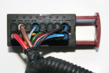
Airtronic D2 D4 D5 wiring loom connector.
The insulation prevents easy testmeter access to the pins. Positive red wire on pin 1, Negative brown wire on pin 10.
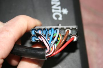
Eberspacher Airtronic connector.
There is similar insulation on the Airtronic heater connector pins.
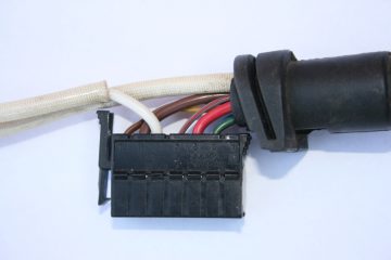
Eberspacher D1LC Compact wiring loom.
Eberspacher D1LC Compact loom connector.
Positive red wire on pin 5,
Negative brown wire on pin 11.
Interpreting the Voltmeter readings
Eberspacher voltage monitoring
The Eberspacher heater will shut down if the voltage drops below 10.5 volts or rises above about 16 volts for 20 seconds. I would be concerned if the measured voltage at the Eberspacher regularly dropped below about 11 volts, it may still operate ok but it indicates there is a potential low voltage problem. The maximum tolerable difference between the battery and Eberspacher voltage readings should be 0.5 volts. Ideally it would be less than 0.25 volts.
Battery voltage monitoring
It would be nice if there was a simple set of voltage readings that could tell you how discharged your battery is. I spent a lot of time trying to make sense of published voltage tables.
The fully charged voltage is roughly 12.6 or 12.7 volts for batteries that have been rested, gel type batteries usually slightly higher. One manufacturer quotes the following voltages for batteries with no charge or discharge for 6 hours, ie fully rested before test. 100% charged 12.7v, 80% charged 12.5v, 60% charged 12.2v, 40% charged 11.9v, 20% charged 11.6v, fully discharged 11.4v
Every battery manufacturer quotes different figures for batteries during discharge and there are such wide variations between them it is impossible to make a decision.
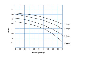
Eventually I found some data for one particular make of battery that could help to explain some of these variations.
The vertical axis shows battery voltage.
The horizontal axis shows percentage of full charge.
The 4 plots are for discharge currents of
5, 10, 20 and 30 Amps with a 100 Ah leisure type battery.
What does the graph tell us about this battery?
If the 100 Ah battery is discharged at 5 Amps the voltage when it is fully discharged is 11.5 Volts.
If the battery is discharged at 30 Amps there will still be 70% charge remaining when the voltage is 11.5 Volts.
By the time the battery is fully discharged at 30 Amps the voltage will have dropped to 9.5 volts.
ie there is a difference of 2 volts between the 5 and 30 Amp discharge rates when the battery is fully discharged.
Your battery may have different voltages to these, they just illustrate the problem. Hence you cannot just measure the voltage to decide how discharged your battery is. What the voltmeter does is to give you clues. If for example last week you measured the voltage before starting the engine and there was only just sufficient power to start the engine and this week the temperature and battery use are similar you would know not to let the voltage drop below what you measured. Similarly you could measure the battery charge state at various times and temperatures with a hydrometer and correlate the measurements with the voltmeter readings. The more you use the voltmeter the more familiar you will become with it and will soon be making good judgments.
Real world measurements
I took some voltage measurements on the D1LCC fitted in my van. It does not have low voltage problems but it could be improved. Both the 12v supply cables (positive and negative) are fairly long, 6.5m, and are 10 mm2 cable. The measurements were taken with a fairly new 110 Ah semi traction leisure battery about 60% charged. The initial battery terminal voltage was 12.2v with no load. When the D1LCC switched on the battery terminal voltage dropped immediately to 11.43v. The voltage measured at the Eberspacher was then 10.98v. By the time the Eberspacher glowpin switched off these voltages had dropped to 11.34v battery and 10.94v at the Eberspacher.
The largest part of the drop during starting was in the battery itself, about 0.8v The loss of voltage due to cables was 0.45v, close to the 0.5v maximum I would accept but double the recommended amount.
That gave me about 0.5v headroom above the cutoff voltage during the critical starting period.
During normal running the Eberspacher draws less current and the cable loss is a lot lower.
Ideally the cable size would be double as the Eberspacher D1LCC and other older heaters take about 20 amps during starting. That would reduce the loss to the recommended 0.25v maximum. One other alternative would be to use the chassis as the return conductor and to connect the two wires in parallel.
I also could replace the D1LCC with an Airtronic D2 which takes less than half the current during starting.
However in my case the arrangement is acceptable and the extra cost and weight of say 25 mm2 cable is not justified. On shows I usually had at least one spare charged battery with me as backup for the inverter so did not need to heavily discharge.
Calculating voltage drop
For those who are interested a little bit of theory.
For copper wire the voltage drop along it is given by the formula E = 0.0167 * I * L / S
where
E = Volt drop Volts I = Current Amps L = Total length of go and return wires Metres
S = Cross sectional area in square mm
So for 2m of cable (1m go + 1m return) at 8 amp loading (D2 or D4 heater) using 2 mm2 cable the volt drop would be E = 0.0167 x 8 x 2 / 2 volts = 0.13 volts
In my real world example above with a cable run 6.5m long (13m total length) using 10 mm2 wire and 20 amps (Older heaters).
E=0.0167 x 20 x 13 / 10 = 0.43 volts which is close to the 0.45 volts actually measured.
Doubling the cable length would double the voltage drop.
Doubling the wire cross sectional area would halve the voltage drop.
Note that these figures do not include voltage drops across fuses, plug and socket connections etc or the battery voltage drop.
Wiring modifications to make voltage measurements easier
The voltage needs to be measured when the glow plug is on during starting which is when you usually need to be away from the heater to turn it on with the control switch. The problem can be so intermittent by the time you have sorted out the testmeter and got access to the terminals, the problem has gone and it starts perfectly. Also D2 connectors have sealant around the wires which makes it difficult to test the end of the cable while the unit is connected. Overcoming these problems is easy if you make a simple wiring modification so the voltage can be easily measured.
The modification consists of permanently connecting two wires to the Eberspacher power wires.
Optionally you can fit a permanent voltmeter to monitor both the battery and Eberspacher voltages.
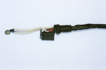
The obvious place to make the connections would be to the short length of exposed wire between the loom and loom connector. Personally I don't like making connections here as the wiring generally experiences maximum mechanical stress close to the connectors. I prefer to make the connection further up the cable and to hide the joint inside the loom sheath which gives a more professional appearance, there are similar joints hidden higher up in the loom. The difference in voltage reading between these two points is negligible and the joint has better mechanical protection.
Open up the loom about 5 to 10 cm from the connector, it may be necessary to carefully cut a slit in the sheath. Ease out the two thicker wires, the positive supply is red, the negative supply is brown.
Join wires onto both of these. Make sure you can identify the positive wire, I used red for positive but any colour will be ok. My method is to remove some insulation, taking great care not to cut the wire strands and to solder the new wires onto them. After insulating each joint the wires can be pushed back inside the loom sheath. Alternatively joints could be made with crimp connectors or any other method that gives a reliable permanent connection. Don't just twist the wires together, although it may work for a while the wires will oxidise, any subsequent movement of the joint causes intermittent connections.
The new wires can exit the sheath at that point or be routed inside the loom itself. I use an electricians wiremans tape or a piece of fairly stiff wire such as the earth conductor removed from a scrap piece of 2.5 mm twin and earth mains cable to thread through the loom. I temporarily fix the wires onto it with insulating tape and pull them gently through the loom. Photos of this are on the remote sensor page.
The new wires will only be carrying very low currents for measuring so can be thin and can be quite long, say up to about 10m if required without affecting the voltage measurement.
The end of the new wires can be terminated on a screw terminal block in an area that is convenient for attaching a multimeter when needed.
However a far better method is to fit a permanent voltmeter. With some additional wiring and a switch the same voltmeter can read both the battery voltage and the Eberspacher voltage, making it doubly useful.
Installing a Voltmeter
In April 2011 I bought a dedicated voltmeter, described on Ebay as Blue LCD Digital Voltmeter 20v, for under £4 including pp. No separate power is needed, it takes power from the supply being measured. Working range: 7-
This is only suitable for 12v heaters, extended range versions are also available which can be fitted on 24v systems. Overall outer bezel dimensions:78 x 42 mm. Cutout dimensions:72 x 39 mm
The switch should be double pole double throw (DPDT), with a centre off position.
Maplin stock two types, 10A toggle JK30H at £3.49 and sub miniature FH05F at £2.49
If you buy from Ebay select one with centre off, ie "on off on" and not "on -
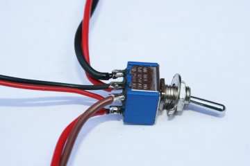
Switch with wires temporarily tacked on to show connections.
Upper red black pair to battery 12v.
Central red black pair meter connections.
Lower red brown pair to Eberspacher.
Measuring voltage at the Eberspacher.
Heater was in use so drawing low current.
Mount the voltmeter and switch in a convenient position, if the voltmeter is close to the switch its wires will not need extending. Run two wires from the battery, here I used red for the battery positive and black for the negative connection. The wires can be thin but remember to include a fuse close to the battery, 1 amp rating is a reasonable choice. Extend the two wires that you joined in the Eberspacher loom, here they were red for the positive and brown negative. Your wires do not have to use the same colours but make sure you can identify which is the positive wire. Solder the wires to the switch as shown. Your connections should be mechanically secure on the switch terminals before you solder them, ie feed the wire through the hole in the terminal or wrap it around the terminal. My connections in the photos were just temporary connections to show where the wires connect so I only tacked them in place.
I used a toggle switch from my spares box which might be slightly different from the one you get but the connection details should be the same. The centre off position allows the meter to be disconnected when not in use. However the current consumption is very low, a 100 AH battery would power the voltmeter for more than a year if there were no other losses or battery deterioration.
The Eberspacher voltage will only be needed very occasionally so the voltmeter's main use can be to monitor the battery.
© 2011 Roy Murkin letonkinoisvarnish.uk